Figure3.6 block scheme ofthe digital circuit for the realization ofthe Digital electronic circuit block diagram Block diagram of the digital circuitry. block diagram of digital circuit
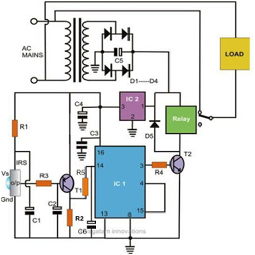
How does NE555 timer circuit work | Datasheet | Pinout | ElecCircuit.com
Block diagram digital circuits Block diagram of the digital computer Block diagram electrical circuit
The block diagram of the digital system on fpga
Simplified block diagram of the digital circuit for image acquisitionProses multiplexer Block diagram electrical circuitBlock diagram of the proposed digital control circuit..
Sequential circuit combinationalHow does ne555 timer circuit work Block diagram of the digital control circuitDiagram block multimeter digital working did electrical principle site instrumentation find android apk electricalacademia.

Fpga architecture diagram
Digital control chapter1 slideTransform sampling Solved draw the block diagram of a basic digital controlBlock diagram computer system components following three combination.
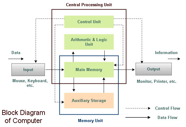
Block diagram digital circuitsBlock diagram of computer Block diagram of computer & types555 timer diagram block circuit chip does ne555 datasheet inside works work eleccircuit pinout look function.

Diagram computer block control chart flow description fundamental vs unit engineering system cpu draw its data logic functional processing alu
Block diagram of digital communication systemBlock diagram of computer with description 2: block diagram of a digital circuit including its sequential andSequential combinational.
Design the digital circuit whose block diagram isElectronic block diagrams solution Solved 1. draw a block diagram of a digital circuit with theExplain block diagram of digital computer system.

Acquisition simplified
Block diagram of the digital logic of a real modulator.Block diagram of the digital circuit for both bs and plc modem Block diagram showing the digital circuit. the input to the circuit isBlock diagram of digital circuitry detailing operation and connectivity.
Digital multimeter block diagramA block diagram representation of the digital circuit used to implement Closed-loop digital control system block diagram (also including the2: block diagram of a digital circuit including its sequential and.